Installation
The device can be installed inside an electrical panel on a DIN rail. Follow the steps below to install the device.
The installation, operation, and maintenance of electrical equipment must be carried out exclusively by qualified personnel. Renua Società Benefit S.r.l. assumes no responsibility for any consequences arising from the use of this material. Qualified personnel are individuals who possess adequate skills and knowledge regarding the construction, installation, and operation of electrical equipment and who have received appropriate safety training to recognize and avoid inherent hazards. REFER TO THE Safety Information SECTION.
Mounting
The figures below illustrate how to mount and remove the device from a DIN rail:
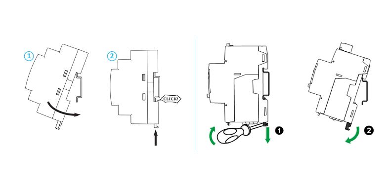
Figure 2 – DIN Rail Mounting and Removal
Wiring
All operations described in this section must be performed exclusively by qualified personnel in accordance with applicable technical and safety regulations.
Installation of the device involves interaction with mains voltages up to 400 V. Failure to comply with safety requirements may result in serious electric shock hazards, equipment damage, and risks to personnel.
The analyzer must be installed downstream of a suitably rated circuit breaker or disconnect switch, clearly identified and located near the device so that it can be easily accessed for isolation purposes.
Before starting any installation or wiring activity, ensure that the circuit breaker or disconnect switch is in the OFF position and verify the absence of voltage using a properly calibrated testing device.
🧰 Required Materials
- RE-431 – Three-phase Energy Meter (DIN rail version)
- DIN rail (35 mm standard)
- Electrical cables (cross-section suitable for the load and compliant with applicable standards)
- Screwdrivers, wire strippers, multimeter
- Cable terminals (optional but recommended)
- Circuit breaker (recommended between the supply line and the meter)
- This technical manual (essential for the correct wiring diagram)
🛠️ Installation and Wiring Procedure (DIN Rail Version)
- Disconnect power from the system and verify the absence of voltage on the conductors using an appropriate measuring instrument (e.g., a properly calibrated and functioning multimeter).
- Install the RE-431-D device on a standard 35 mm DIN rail as shown in Figure 2, ensuring that it is securely attached.
- Connect the current input to the current transformer (CT) according to the wiring diagram, ensuring the correct correspondence between phases and inputs:
L → CT
This operation must be performed before mounting the CTs on the power conductors to ensure correct phase association.
- Mount the current transformer (CT) on the phase conductor (L).
It is essential that the directional arrow marked on each CT is oriented from the measurement point (meter or source – identified as "K") toward the load (electrical panel – identified as "L"), as illustrated in the figure below.
Incorrect CT installation may compromise the accuracy of current measurements and energy flow direction detection.
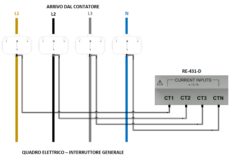
Figure 3 – Current Transformer (CT) Installation
- Connect the phase voltage inputs [VOLTAGE INPUTS] according to the supplied wiring diagram. The use of a dedicated circuit breaker (2-pole, 6 A or 10 A rating, minimum breaking capacity 4.5 kA) is strongly recommended for single-phase installations. This solution improves safety, efficiency, and regulatory compliance for the following reasons:
- Provides adequate protection against overloads and short circuits, reducing the risk of permanent damage.
- Allows functional isolation of the equipment, facilitating safe maintenance, inspection, or replacement without affecting the power continuity of the installation.
- Meets the requirements of applicable technical standards (e.g., IEC/CEI 64-8) and aligns with industry best practices.
- Simplifies wiring organization, making fault identification and troubleshooting easier.
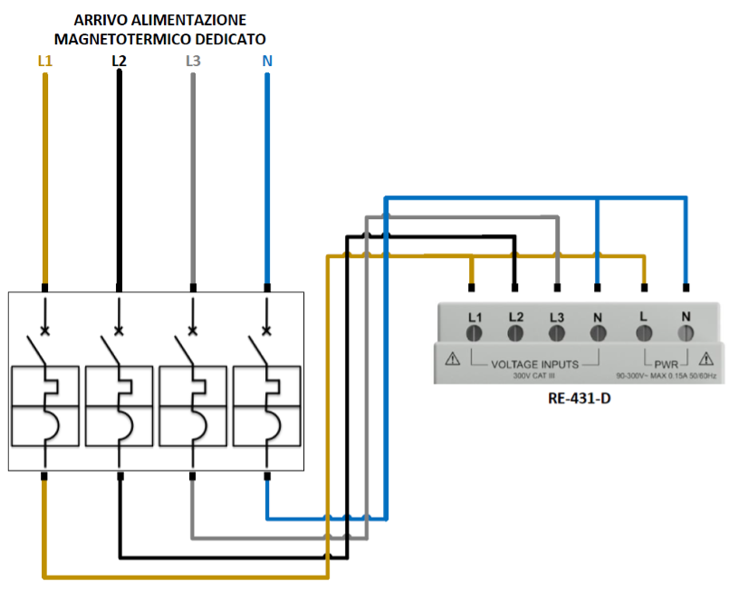
Figure 4 – RE-431-D Power Supply Connection
- Connect the [POWER INPUT] terminals to provide power to the device.
Whenever possible, it is recommended to connect the power inputs to an auxiliary or preferred power line to ensure continuous operation of the analyzer even in the event of faults or interruptions on the monitored electrical lines.
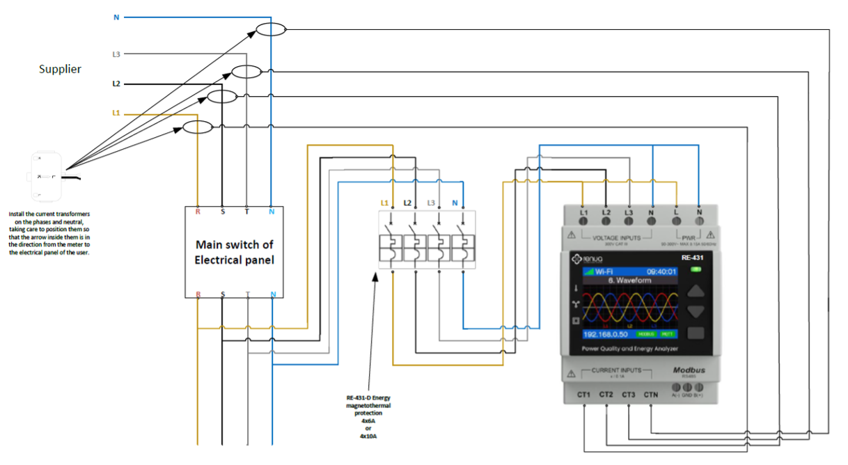
Figure 5 – RE-431 Energy Meter General Wiring
Wireless Network Connection
To ensure a stable and reliable connection, the Wi-Fi signal must be adequate and the network must have Internet access.
The analyzer is operational (measurement, display, Modbus) even without a Wi-Fi connection. To connect it to the network, start the guided configuration procedure (Wi-Fi Setup) from the on-screen menu:
Settings → Communication → Network → Wi-Fi → Wi-Fi Setup
When the procedure starts, the analyzer activates a temporary Access Point (AP), with a 5-minute timeout. Using a computer or mobile device, open the list of available Wi-Fi networks and select the network identified as RE-XXXXXX.
After connecting, follow the instructions displayed on the Wi-Fi configuration page that will automatically open in the browser of the device connected to the analyzer's Wi-Fi network.
For on-screen menu navigation and PIN-protected access, see the Display and Menu and Security and Access pages.
Press Scan networks to display the list of available wireless networks. Alternatively, Enter manually lets you type the network name directly.
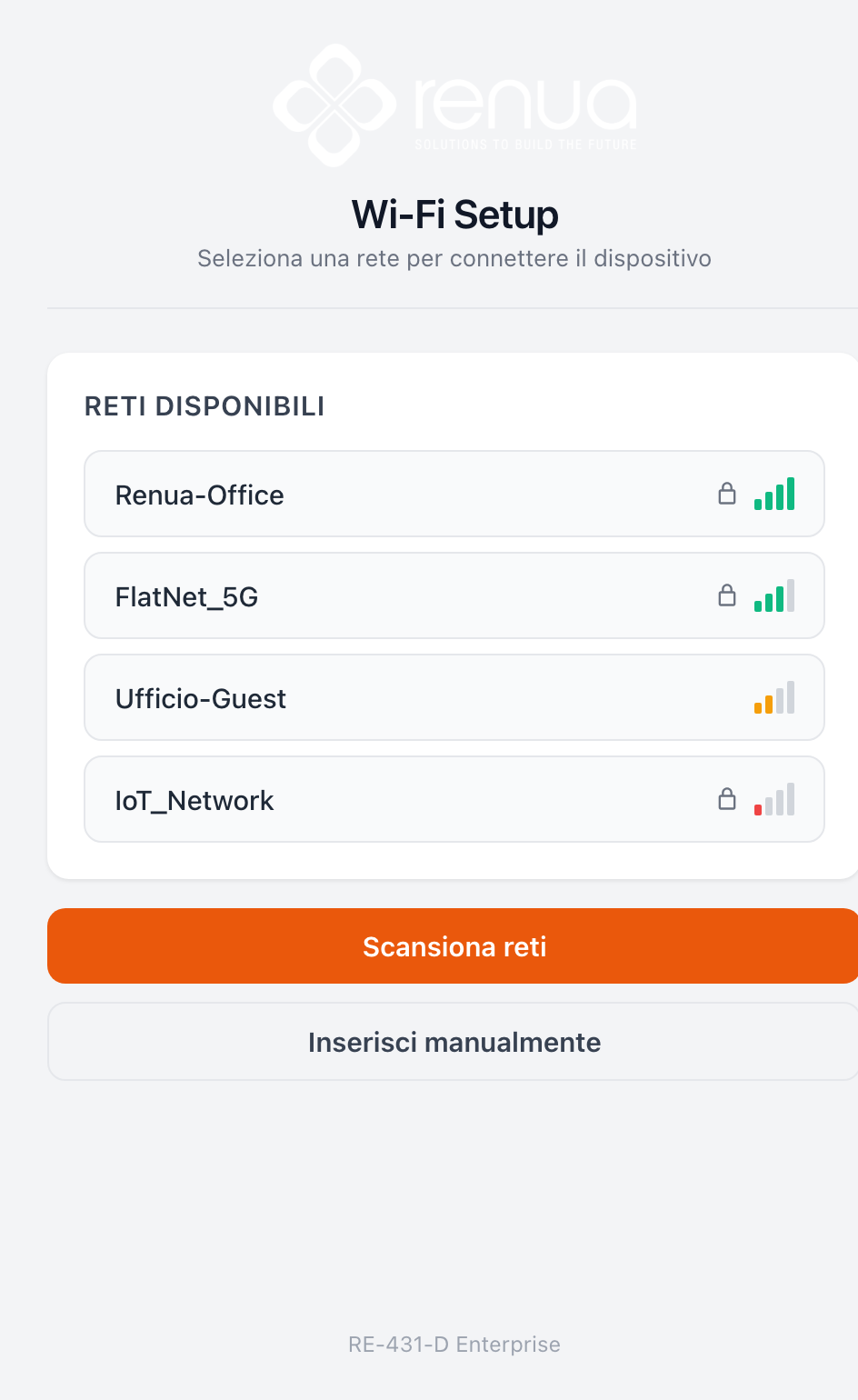
Figure 6 – Wi-Fi network scan
Select your network from the list, then enter the password. You can leave the IP address assignment automatic (DHCP) or turn it off to set a static IP. Press Connect.
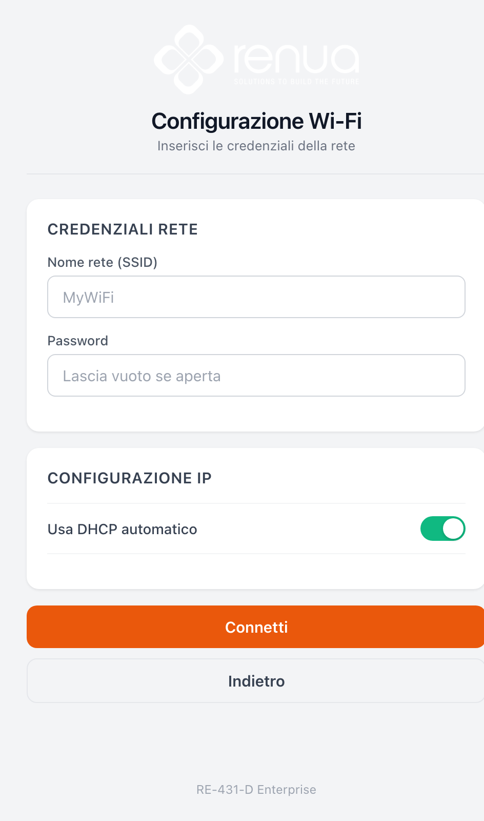
Figure 7 – Entering the network credentials
If the connection is successful, the analyzer’s IP parameters are displayed. Press Save and exit to complete the configuration.
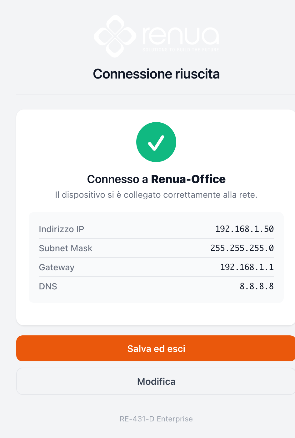
Figure 8 – Connection successful
Then access the device’s integrated web interface using the IP address obtained during the connection (see Security and Access for enabling the Web Admin).
For stable operation, the Wi-Fi signal level should be greater than -70 dB.
Measurement data is transmitted to the cloud. Data access is provided through the Web Dashboard.
Functions
Analyzer Features
The analyzer measures line current and voltage and displays RMS values in real time. It also calculates power factor, active power, reactive power, and apparent power.
Energy Readings
The analyzer calculates and stores total and partial energy values for active, reactive, and apparent energy.
Energy values can be viewed on the display. The energy unit automatically changes from kWh to MWh (and from kVAh to MVARh) according to the measured value.
Analyzer Operation
Overview
The analyzer features a front panel that includes a status LED indicator, a color graphic display, and a set of contextual function buttons.
These elements allow the operator to intuitively access operational information and to view, configure, and modify operating parameters according to application requirements.
The navigation menu allows users to view, configure, and reset parameters. The full description of the measurement pages and the menu structure is provided in the Display and Menu page.
Display Screen Overview
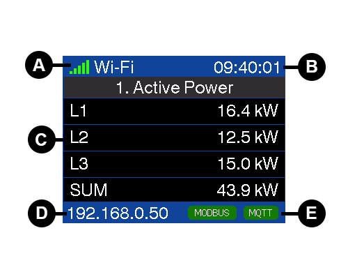
| A | Wi-Fi Signal Strength and SSID |
| B | Time – Local Format [HH:MM:SS] |
| C | Screen Content |
| D | Wi-Fi Interface IP Address |
| E | Status Notifications |
Status Information
The status LED on the front panel indicates the current operating status of the analyzer.
The icons in the following table indicate the LED status:
 = Off = Off |  = Flashing = Flashing | = Solid |  = Solid = Solid | |
| Status LED | Analyzer Powered Off | Startup Phase | Not Connected | Analyzer Connected |
Reset and Factory Settings Restoration
The restore operations are available from the on-screen menu or from the Web Admin:
| Restore | Path |
|---|---|
| Reset Wi-Fi settings | Settings → Communication → Network → Wi-Fi → Reset Wi-Fi |
| Reset Web password | Settings → Security → Reset Web Password |
| Reset energy counters | Settings → Measurement → Reset energy counters |
| Reset display PIN | Hardware combination at startup (see below) |
Hardware reset of the display PIN
If the menu access PIN is forgotten, it can be cleared at startup:
- Disconnect power from the device and then restore power. During the startup screen, simultaneously press and hold the UP and DOWN buttons for about 5 seconds, until the countdown and the confirmation message of the PIN reset appear.
At the next menu access you will be asked to set a new PIN.
For details on the restore procedures and on access, see the Security and Access page.
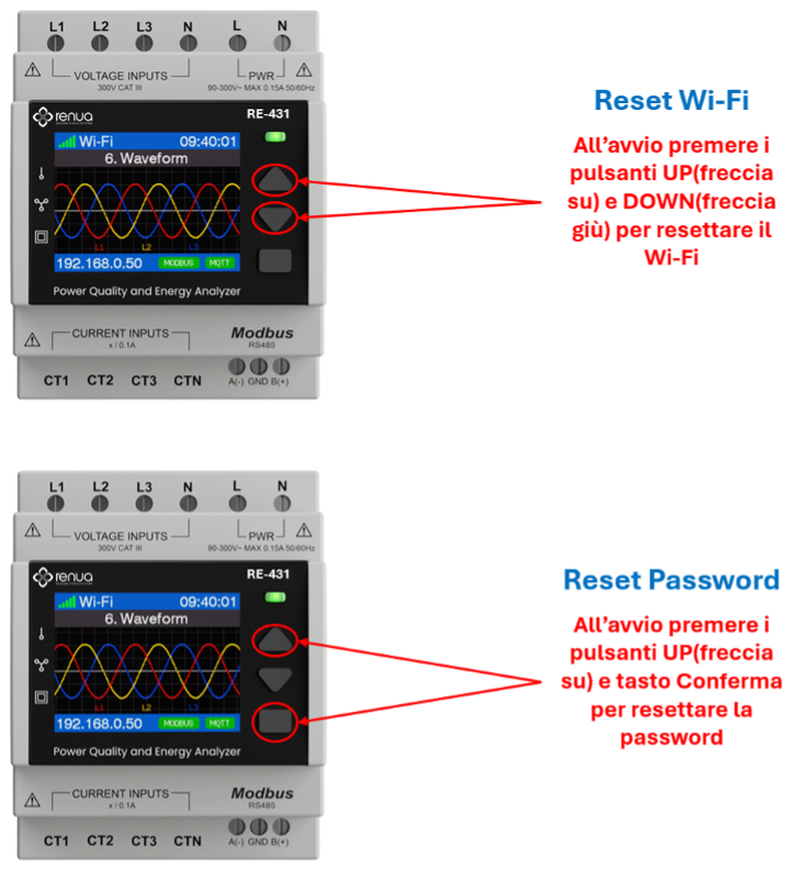
Figure 10 – Hardware reset of the PIN at startup
Maintenance and Troubleshooting
Overview
The analyzer contains no user-serviceable components. For maintenance or repair operations, please contact technical support at support@renua.it.
- Do not open the analyzer enclosure.
- Do not attempt to repair analyzer components.
Do not open the analyzer. Opening the analyzer voids the warranty.
Diagnostic Codes
If anomalies are indicated by the status LED and/or error icons on the display, the system will automatically show a diagnostic code corresponding to the detected condition. If the issue persists after applying the recommended corrective actions, contact technical support.
| Diagnostic Code | RE-431 | Description | Possible Solution |
|---|---|---|---|
| - | ✅ | Status LED appears to be off | Restart the analyzer by powering it off and on again |
| - | ✅ | Buttons do not respond | Restart the analyzer by powering it off and on again |
Maintenance and Troubleshooting
| Diagnostic Code | RE-431 | Description | Possible Solution |
|---|---|---|---|
| 001 | ✅ | The analyzer stops due to an internal error | Restart the analyzer by powering it off and on again |
| 002 | ✅ | The analyzer is operating. Frequency settings do not match measured frequency | Correct the frequency settings according to the nominal network frequency |
| 003 | ✅ | The analyzer is operating. Wiring settings do not match wiring inputs | Correct the wiring settings according to the actual wiring inputs |
| 004 | ✅ | The analyzer is operating. Phase sequence is reversed | Check cable connections or correct the wiring settings |
| 005 | ✅ | The analyzer is operating. Date and time have been reset due to a power interruption | Restart the analyzer by powering it off and on again. Verify the device's Internet connection |